We no longer offer turbo kits through Tearstone Performance, but we have gotten many emails asking how to build one. We present to you the published parts list for building your own V6 Turbo kit. Please do not email me any questions or quotes for a turbo kit. Simply leave a comment about the article below.
This is published for the intent of educational purposes. Tearstone Performance will not be held liable for any damage caused as a result of this published information. Furthermore, Tearstone Performance is free of any liability for anything resulting on the use of this information. This document is subject to change.
In a nutshell, this is the parts list for a Mitsubishi 6G72/74 single turbo kit.
Turbo
- Master Power T4 Turbo Part# 810007
- Oil Feed Fitting
- 1/8 X 1/8 FIP X MIP ADPT
- 1/8 FIPXMIPXFIP BS STREET TEE
- 1/4 X 1/8 MALE FLARE X MIP ADPT
- 1/4 X 1/8 BS M FLARE X MIP ELB
- Oil Drain Fittings
- T4 Housing Oil Drain with 1/2″ Female
- 1/2 MIPXFIP BS 45 STR ELBOW
- (2) 3/4 X 1/2 HOSE BARB X MALE ADPT
- Stainless steel feed line
- 3 Foot 3/4″ Pushlock return hose
- Turbo Hardware
- Gaskets
- T4 Inlet Gasket
- Oil Drain Gasket
Hot Side
- 2.5″ Collector Pipe (Requires Fabrication)
- 2.5″ Downpipe – Turbo to Catback Pipe (Requires Fabrication)
- Wastegate Recirc Tube (Requires Fabrication)
- 38mm Wastegate
- T-Clamps
Cold Side
- 3.0″ Compressor Inlet Tube (Requires Fabrication)
- 2.5″ Compressor Discharge Tubing (Requires Fabrication)
- Treadstone TR6 Intercooler Core Size, 6″ X 22″ X 3.5″
- Blow Off Valve with recirculation
- Universal Fit K&N Cone Air Filter (4.5 inch I.D. outlet)
- M.A.F. Adapter for Mitsubishi Applications
- Recirculation Hose
- Valve Cover Breather Hose
- Intercooler Hardware
Coupler Kit
- (2) 2.5″ Straight
- (1) 3.0″ Straight
- (4) 2.5″ 45 Degree
- (2) 2.5″ 90 Degree
- (1) 3.0″ 90 Degree
Hose Clamp Kit
- (16) 2.75″ Clamps
- (4) 3.25″ Clamps
440cc Injector Kit
- (6) 42# Injectors
- (4) Injector Spacers
- (4) M8 60mm Bolts
- (6) Holley Fuel Injector Connectors Part # 534-112
Fuel/Electronics
- Walboro 255lph Fuel Pump
- Greddy E-Manage
- Greddy Ignition Harness
- Greddy Injector Harness
Use this as a guide to get a better understanding of what and why you need the parts to successfully develop a turbo kit for your car. Please do not be mislead that you are not able to achieve this, you simply just need a shop that can weld mandrel bent piping together and the parts for them to put it on. A lot of shops won’t touch this car because of how fragile the engine is along with the difficulty in tuning the car.
Everything below is prefaced below first directing you to read the 6G72 limitations article here: 6G72 Limitations
This vehicle was never intended to be turbocharged, and keep in mind that what the Galant guys already realize, the Eclipse/Stratus and Sebring coupe is a passenger sedan with a sporty shell. Below is a diagram of other recommended upgrades that should be performed to handle the given amount of wheel horse power. Note that each horsepower level that supersedes the lower horsepower level carry those recommendations as well.
| Horsepower | Recommended Upgrades |
| 300whp | 5spd MT – Clutch, possibly an aftermarket or hardened stock differential depending on how hard you launch, possibly axles depending on the stiffness of the clutch.4spd AT – Transmission cooler is a must, especially with a front mount intercooler.3″ exhaustAftermarket forged pistons |
| 400whp | Aftermarket ignition to either drive the single coil distributor or convert to coil packs. |
Turbo
The Master Power T4 turbo chargers that were used with the kits are manufactured in São Marcos, Brazil. A lot of people accused us of including Chinese turbo chargers, but in fact they are far from it. These turbo chargers are undoubtedly shine above Turbonetics and Precision in fit & finish. The hot side castings were pristine and the cold side was nearly perfect. More information about Master Power can be found at their website here: Click Me!
The T4 that was used is what’s commonly known as a 60-1 turbo. It was specifically used for the goal of achieving no less than 400whp. Unfortunately, this dream was never realized due to the short run of the kits and customers that do have kits maintained the minimum amount of boost the wastegates were set at.
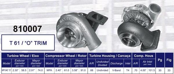
For the purposes of what you are truly going to end up with on your Eclipse based platform, simply look no further than a T3/T04e. A 50 trim turbo will get you up to the 450whp mark and give you some nice spool time down low.
Oil Fittings
The turbo must be lubricated, the most efficient way to provide a constant flow of oil to the turbo is by tapping the block and returning it back into the oil pan. Your stock oil pressure sensor uses a standard 1/8th fitting which can be screwed off and you install a series of brass fittings in between the sensor and the block. The oil will travel through a stainless steel line into the top of the turbo. Gravity then takes over from there and bathes the internals of the turbo, primarily the shaft and bearings. Then like a sink, it drains down into a big hose which gets routed up high in your oil pan.
Series of feed adapters is installed like this:
1/8 X 1/8 FIP X MIP ADPT <– Adapter to go into block
1/8 FIPXMIPXFIP BS STREET TEE <– Goes into the adapter
1/4 X 1/8 MALE FLARE X MIP ADPT <– Goes into the tee
Stainless Steel Hose <– Connects the 1/8 male flare from the block to the 1/8 male flare to the top of the turbo.
1/4 X 1/8 BS M FLARE X MIP ELB <– Into the Turbo
It’s very important that you tap your upper oil pan for the drain, close to where your dipstick comes into the upper oil pan. There is a flat spot which has proven ideal for this location. Long ago we found out tapping the lower oil pan created a backup of oil in the drain. With high pressure oil going into the top of the turbo, and the drain clogged up with oil because the lower oil pan is always full of oil, the oil must vent somewhere. The oil began seeping right out the seals of the turbo. This made for quite an embarrassing situation on the street when ever the car was on a level grade, it would begin to billow smoke out of the exhaust. If you were on an incline the oil would flow towards the back of the engine away from the drain fitting and not smoke. Either way, this is easily avoided.
Series of drain adapters is installed like this:
T3 or T4 housing drain fitting <– installed on the bottom of the turbo with a 1/2 fitting.
1/2 MIPXFIP BS 45 STR ELBOW <– goes into drain fitting
3/4 X 1/2 HOSE BARB X MALE ADPT <– goes into 45 degree elbow
3/4″ Push lock hose <– Connects the 3 foot 3/4″ drain from the turbo to the upper oil pan on the block.
3/4 X 1/2 HOSE BARB X MALE ADPT <– installed into the upper oil pan
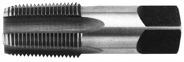 The fitting on the oil pan can be installed using a 1/2″ hole saw and a 1/2 – 14 NPT Pipe Tap. The metal of the upper oil pan is thick enough to do this so you can screw the 1/2″ fitting right in. Of course with all the fitting you will need to use thread tape to prevent leakage.
Turbo Hardware
You are going to need nuts and bolts to secure the turbo to the inlet and outlet flanges of the turbo. If you are using a vband style outlet, you will need a vband clamp that is typically supplied with the flange. Size is based on the turbo you get and you these parts are relatively easy to find. At the time of this writing I don’t have notes for the bolt sizes and lengths you will need but you can measure the thickness of the flange/turbo flange along with the hole diameters to figure out which bolts you can pick up from your local hardware store. Always use lock washers and nuts. You can’t use locking nuts (the nuts with the plastic ring in them) because the plastic will melt.
Gaskets
You will need a gasket to sandwich between the T3/T4 flange which is welded onto your downpipe and the inlet flange of the turbo. If not you will undoubtedly have an exhaust leak. A gasket between the turbine outlet and the downpipe is not necessary but recommended.
Hot Side
Exhaust Piping
In your endeavors in understanding how turbo systems work, the primary principle to understand is that turbochargers are powered by wasted energy expelled from your engine in the form of exhaust gases. These exhaust gases are routed from both manifolds from your heads into the inlet of the turbo. After the rush through the turbine housing, they are then dumped out through your downpipe into your catback and out into the air behind your car.
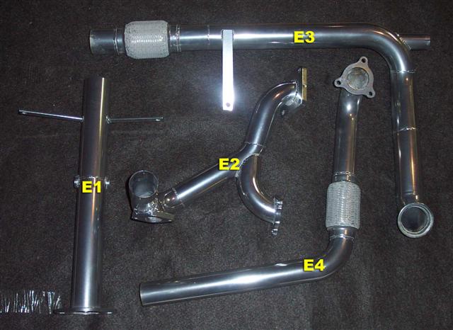
This portion of the kit is probably the most difficult hurdle to get through because it will be necessary for you or someone to fabricate this portion for you. You simply cannot pick these parts up on EBay, and you can’t piece them together with any piping. The most cost efficient way to produce this piping is using mild steel, because it’s the easiest to weld and is the cheapest. The next step up is stainless steel which most cat backs today are built with but the price goes up about another 50-75%. For the fit and finish of the piping you would probably want to ceramic coat the mild steel or polish the stainless steel. Power coating cannot be used due to the temperatures that the piping sustains from the hot exhaust gasses.
Building this piping the most cost effective way is to retain the use of your stock manifolds. Granted, you could have a tubular manifold, and ideally if it’s built properly you will get better gains but it can get very expensive. The kits that we offered back in the day retained the use of the stock manifolds and we never had any problems hitting the horsepower numbers that we were looking for at the time. For better flow characteristics the Fed Spec manifolds which are stamped steel seem setup for better flow than California spec manifolds. California spec vehicles became the standard in 2001, and you will know you have those manifolds if you have 3 catalytic converters on your car. If you have a fed spec, then you only have one cat and that’s at the bottom of the car. We don’t have any hard numbers on what flows better than what, so it’s really difficult to say which one is better but they all have pros and cons.
- Fed Spec manifolds were designed with performance in mind but are made out of stamped steel welded together, potentially a weak point in that design when used in a turbo application.
- California Spec manifolds were designed to accommodate a small catalytic converter between the head and the bottom of the engine. They are cast iron and indestructible.
- Tubular manifolds will provide the best performance, but will be expensive to build and are potentially subject to cracking.
The “Y” pipe that joins the two manifolds together that will feed the inlet of the turbine housing should be designed in such a way that it goes above the cross member holding the front motor mount in place. The biggest mistake I’ve seen with kits that run the pipe underneath the cross member are just a recipe for disaster. The piping is a rigid mounted system bolted directly to the manifolds which are tightly bolted to the block of the heads. With the limited ground clearance you will put your motor mounts and piping through undue stress. It pretty much makes it so you can’t even lower the car. Some have even attempted to use their after market header manifolds and run into this same problem as well because the manifolds are too long to efficiently design the piping in such a manner to route it above the cross member.
On the “Y” pipe, you would install an external wastegate assuming your design did not include an internally gated turbo. The wastegate is used to “bleed off” exhaust to control the amount going into the turbo which in turn controls boost. Without a wastegate the full load of the exhaust will dump right into the turbo and exponentially build boost until your engine pops. The wastegate can be recirculated into the exhaust stream after your turbo to alleviate the loud nasty sound that comes with venting a wastegate out into the open.
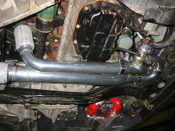
Another piece of this pipe puzzle is building the downpipe to smoothly route from the outlet of your turbo out to the back of the car. There has been debate on 2.5″ or 3.0″ downpipe and that really comes down to your preference with the power you are going to make. If you want to exceed 300whp, then a bigger downpipe will be necessary. The big downside with the 3″ downpipe is that it creates another clearance enigma to safely get it to clear everything. Consider that most turbos that you are going to use have a 2.5″ outlet anyways, so a 3″ wouldn’t be necessary and is fine to shift the focus of the 3″ when it comes to your cat back. Keep in mind also that your downpipe size may benefit a lot more if you match it up to the outlet of the turbo.
A 38mm wastegate will be fine with the amount of horsepower you are going to make with this application. When selecting a spring, keep in mind that the spring sets the lowest amount of boost you can make without a boost controller. After that you should buy a manual or electronic boost controller to raise it beyond that point. The real cheap way to control boost say if you wanted to bump it up is to put in a stiffer spring rated for a different amount of boost. But you lose the ability to control your boost on the fly.
Cold Side
Inlet Tube
Another portion of the kit that requires fabrication is where air would be sucked in through the air filter, through the MAS attached to the inlet of the compressor side of the turbo. There is of course a particular short cut that could be made to not necessarily have to fabricate a tube but just use a 90 degree coupler and plumb the Mitsubishi stock MAS adapter into that, then attach a filter right to the MAS with the MAS adapter.
The tube on the kits we used to send out were attached with a 90 degree coupler off the turbo and a pipe was run up next to where the battery was for a cleaner look. The knee-jerk perception by some was that the filter was right in the engine bay pulling in hot air. You must understand that the mere act of compressing air alone heats it up anyways and that’s where the intercooler comes in. The only possible caveat to this thought process of course is if you run such a low boost level you don’t use an intercooler then you may want to alter this design by using a 90 degree coupler and point it downwards allowing the filter to be towards the bottom of the front of the car. But this also opens up the possibility of gulping down water being sucked up from some deep puddles. Fortunately, when I had my car setup this way one time I never ran into this issue but living in Florida I feared hard rains and driving for this reason.
It’s very important to understand that the placement of the stock air flow meter (or MAS) must come before the turbo so that air is sucked through it. The stock configuration of how the car comes stock was designed to have air sucked through it. The same MAS is also used on the 3000GT along with the previous generation of DSMs (Eclipse/Talon) platforms that were turbo charged as well. There are others that have designed kits to blow through the MAS with some odd results.
Instead of the ‘suck through’ method, putting the MAS after the turbo is pushing air through the MAS. The MAS is a very delicate part and was simply not designed for these pressures. Also blowing through the MAS causes irregularities in air flow which potentially will confuse your ECU causing erratic idle and run conditions. At higher levels of boost the honeycomb has even collapsed inside the MAS. Imagine the potential destructive nature of where that honeycomb could do if it broke part and got stuck in the throttle body! Bottom line the MAS can do a better job of understanding air flow if the air comes in under natural vacuum like it’s supposed to.
Discharge Tubing
This portion of the fabrication can be a number of different ways. Back in the heyday of Turbo Eclipses here in Florida there was quite a few vehicles that were turbocharged and they all seemed to have the piping from the outlet of the compressor to intercooler then to the throttle body a totally different way. Since the most popular method of placing the turbo slightly above the transmission and behind the driver’s side fan here are a few different ideas.
- Non-Intercooled – This should only be done in a 6psi or below condition due to the low amount of heat generated by the turbo and the size of the turbo you are using. All you need to do is fabricate a pipe from the compressor housing of the turbo to the throttle body.
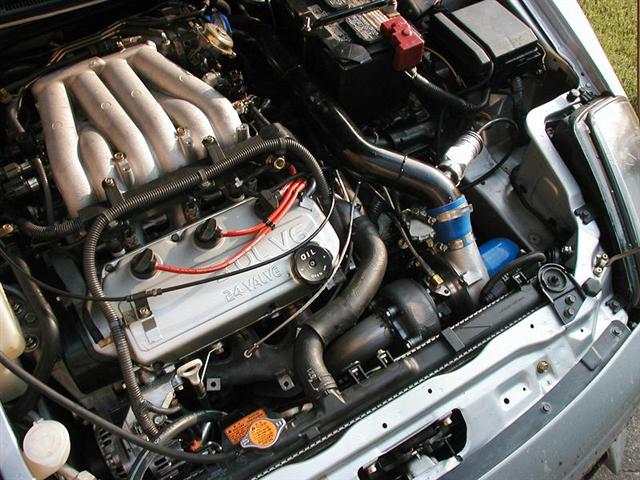
- Over The Front Exhaust Manifold – This is possible if you push your A/C lines around and eliminate the power steering ring from the passenger side, you could route a pipe over to the passenger side of the engine bay, straight down to feed a front mount intercooler. On the opposite side of the intercooler another series of piping would route along the same path a cold air intake would take to get to the throttle body.
- Through the Front Bumper Support – Mike Rule came up with a very creative way to run piping by removing a portion of the front pumper support to allow a pipe to run through the top of it. Essentially, you would spin the compressor to point the outlet towards the ground, loop the piping around on the driver’s side to the top of the modified bumper support, then a downward u-turn into the intercooler then take the cold air intake path to the throttle body after leaving the intercooler.
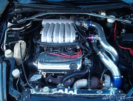
- Side Mount Intercooler – One of the more efficient ways to simplify the piping is to install a side mount intercooler behind the fake vents of the front bumper cover. You would want to cut the fake vents out for the best air flow. The compressor would be pointed at the ground, the piping would make a 90 degree into the intercooler, then the outlet would be right there as well to travel the path of the cold air intake.
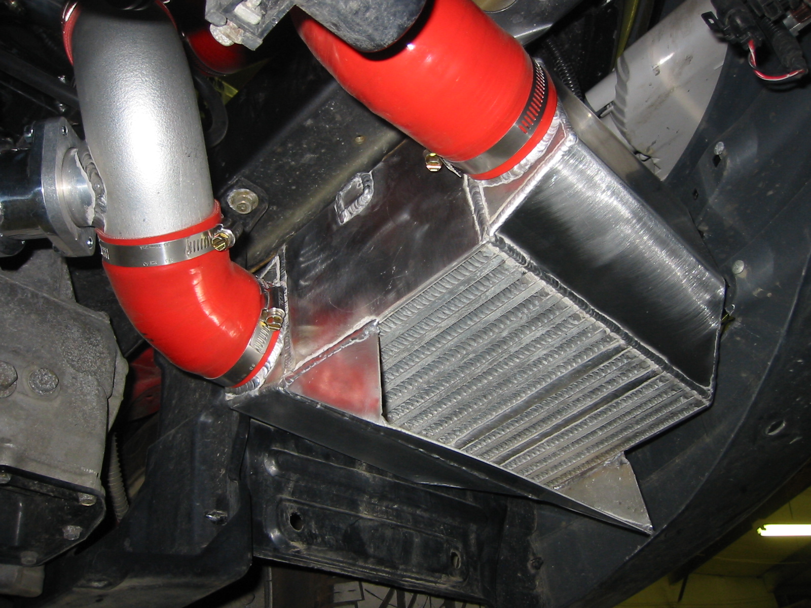
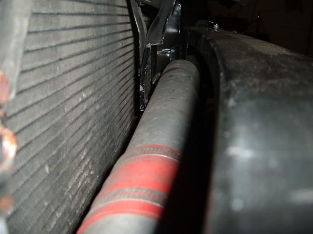
- Behind the Front Bumper Support – Since the design of the front mount was in demand, a new design for the kit was born run the piping from the driver’s side in between the bumper support and the A/C condenser to enter the intercooler from the passenger side. From the intercooler, it would travel the path similar to a cold air intake.

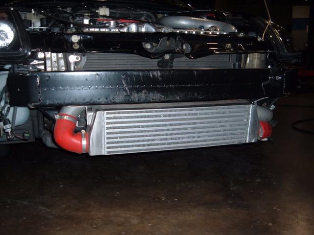
- Water to Air Intercooler – Probably the most efficient way to cool your charge is with a water to air intercooler. Using the same route as a non-intercooled path, you would cut mid way into the piping and plumb in the intercooler which is filled with chambers that water flows through. There are two nozzles the water flows through on the intercooler, which is pumped from the reservoir, into the intercooler, out into a heat exchanger and dumped back into the reservoir.
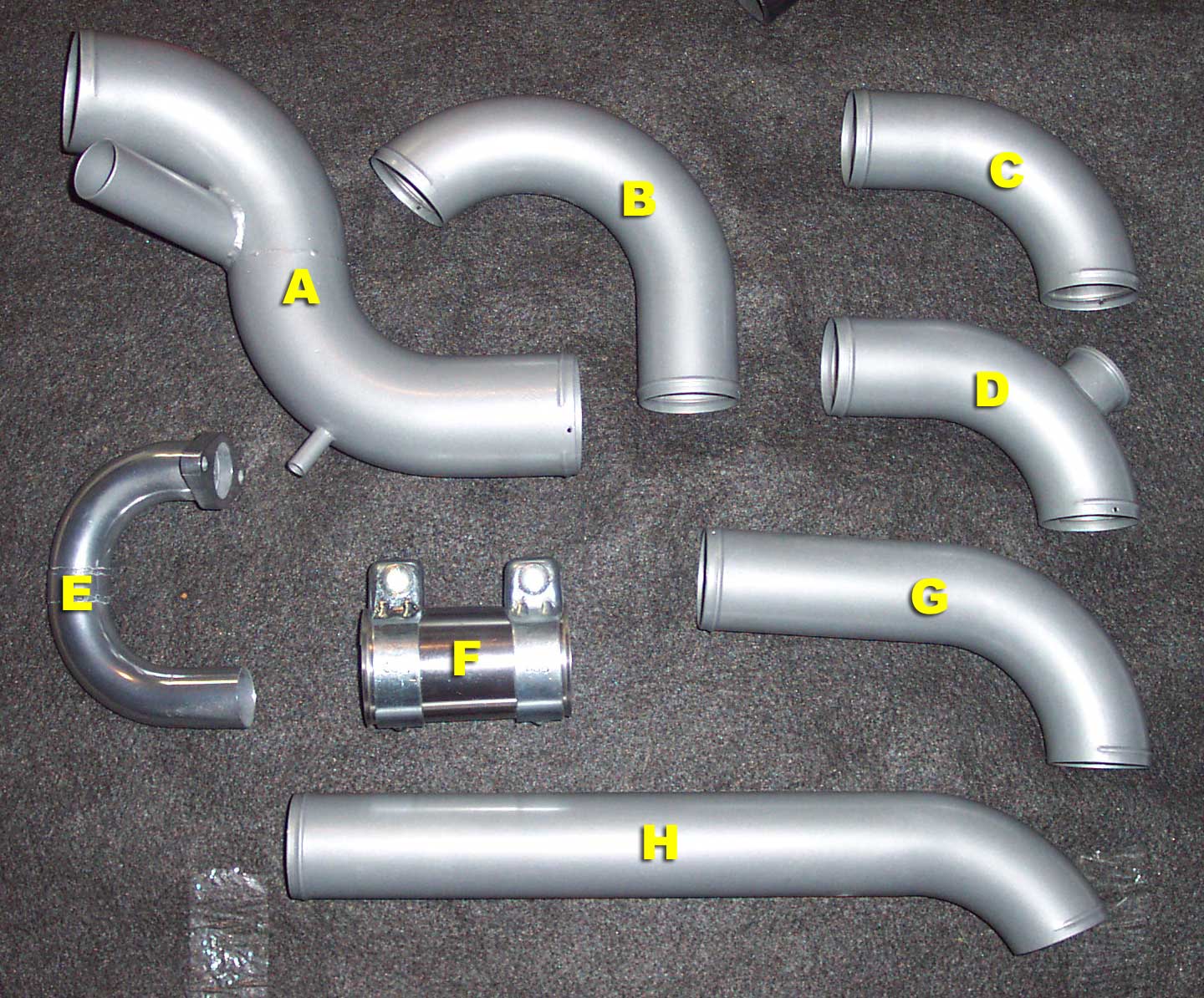
A Cold Side, connects to MAS, BOV Recirc, and Turbo inlet
B Cold Side connects to B and turbo outlet
C Cold Side, connects to H and intercooler
D Cold Side, BOV Flange, connects to intercooler
E Wastegate Recirc
F Exhaust Coupler
G Cold Side, connects to H
H Cold Side, goes behind intercooler/bumper support
* Not pictured is the long pipe that goes from the intercooler to the throttle body
Intercooler and Hardware
When the kit was very first introduced it was built with a side mount intercooler. But as soon as we brought the kit to everyone’s attention immediate the overwhelming demand was a front mount intercooler. Some or most people that set out to go through the trouble of installing a turbo kit on a car that was not turbocharged from the factory was to wear a badge of accomplishment in a sense. Plus a front mount intercooler just looks cool and really fulfills that boy racer look that the demographic of this scene goes for. The particular size we were using adequately filled up the wide mouth of the 2000-2002 front bumper covers and completely filled in the mouth of the 2003-2005 bumper cover.
The front mount intercooler while it looks cool and is a mechanical way to cool air does have one draw back. The car was designed with a particular sized opening to accommodate air flow for the power steering ring, A/C condenser and the radiator. By placing an intercooler in front of all these heat exchangers automatically decreases the efficiency threshold of the radiator to work the way it’s supposed to. Note that cars that come turbocharged from the factory commonly use side mount intercoolers which place them safely to the side. The Evo however does use a front mount yet also has a large opening between the top of the bumper cover and the hood to accommodate the extra airflow needed to keep the A/C condenser and the radiator efficient.
A water to air intercooler could be placed between the compressor outlet of the turbo to the throttle body. In terms of piping, this is a much simpler way to cool the charge from the turbo. However, you need a pump, reservoir and extra tubing to accommodate the flow of water. With the addition of the pump presents another moving part to the equation which could present another mechanical point of failure. The bonus side of using this method of intercooling is that you can load up your reservior with ice at the track. These types of intercoolers are not cheap and for multiple reasons they are the most unpopular although they are the most efficient.
Coupler Kit
We used 3 ply silicone couplers that were custom made by the same manufacturer that supplies turbonetics. They were thin walled silicone with multiple layers of stitching. I would recommend staying away from rubber and definitely stay away from the rubber hose section at your local home or hardware store. Depending on the design of the piping this will significantly vary based on size and angle.
Hose Clamp Kit
As long as the piping is bead rolled at the end, the typical size worm clamps that you pick up at any auto store will work fine even for high levels of boost. At the point you reach say 20+ psi, you may want to consider t-bolt style clamps. Bead rollers are expensive, and your shop may not have this that builds your piping. You may be forced to tighten down your worm clamps with a 9mm socket and call it a day. Your results may vary in this realm, but worm clamps have never failed us. The clamps we enclosed with the kit were oversize by 1/4 of an inch bigger than the outer diameter of the piping to use it on to fit perfectly without an excess of band hanging out of the other side. If you use really thick couplers you may want to step it up another 1/4 of an inch.
440cc Injector Kit
The kit that was developed for around 300whp was using top feed 440cc/min or 42lbs/hr Ford Racing injectors enclosed slightly modified to clear the stock fuel rail. Depending on what you find in terms of top feed injectors, some injectors may need to have some of the plastic cut off the top of it to fit the stock fuel rail and some may not.
In order to determine what injector sizing you need to understand BSFC, injector duty cycle and the amount of horsepower you are aiming to achieve with the current iteration of the setup. All of these factors ultimately contribute to the success and reliability of your setup. This is also based on the assumption that you are using the stock fuel pressure. Adding more pressure to rail alone without properly sizing your injectors is not the most ideal way to increase your fuel output.
BSFC is an acronym for Brake Specific Fuel Consumption. This factor is derived from the combination of fuel consumed per the power or horsepower that is produced. Since this factor is common over a number of engines, I won’t go into too much detail here. The BSFC factor for a naturally aspirated engine is .5, supercharged is .6 and turbocharged is .625.
Injectors are controlled electronically through the ECU and the duration of the time the injector is activated is the Injector Pulse Width (IPW). Injectors only fire once in every cycle of the 4 stroke engine. Using simple math, if it takes 50 milliseconds for a full 4 stroke cycle. Also keep in mind that a 4 stroke cycle is 2 engine revolutions. one intake and compression, the second revolution for power and exhaust. If the IPW is 15 milliseconds out of the 50 milliseconds it takes to complete a full cycle, then the duty cycle of the injector is 30%. It is generally accepted that most injectors will max out at 80% duty cycle, so we’ll use that figure in the equation to determine your injector size.
Keep the horse power number pretty realistic for your setup. I say shoot for 300 or 350 for your initial setup, you can always upgrade to bigger injectors later if you plan on a grand setup. This document is aimed at getting you familiar with a basic setup and getting it working successfully. Do your best to stay realistic in your goals and just enjoy what an extra 100 horsepower can do for you.
In order to determine the size of your injectors, multiply desired horsepower by your BSFC. Multiply the duty cycle (80% = .80) by the number of injectors we are using (6). Divide those two numbers and you will arrive at the lbs/hr injector rating. To convert that into metric, multiply it times 10.50.

Fuel Pump
Making more power with the turbo requires the same in compensation with the fuel that needs to be provided as well. It is understood that stock fuel pumps can handle about 20-25% more than they can put out for the stock configuration of the car. The pump is over engineered for a prolonged life from overheating or just dancing around the point of failure from being maxed out.
We’ve tested out using the stock fuel pump running 5.8psi and making about 250whp. At the middle of 3rd (Sporty) or 4th (5spd) under a wide open throttle drag the engine would hit what seemed like a rev limiter right in the middle of the RPM range. Basically the stock fuel pump couldn’t supply enough fuel to the engine so it wouldn’t allow the car to make anymore power. Upgrading to a Walboro is part of the project, and we have a good set of instructions here: https://tearstone.com/shop/Fuel-Pump-Install-992000-2005-Eclipse/Stratus/Galant.html
Electronics
Without going into too much depth, there is a number of products on the market right now that could be used to accomplish this task. We sent out the Greddy E-Manage blue out with the kits because they were cost effective, and they did the job. There are newer options such as the AEM FIC or simply figuring out a way to wire in a AEM EMS standalone to control everything. A real budget option is also finding someone to build you a MegaSquirt II controller which some people have had mixed success with.
Make sure you understand what it is that you are buying. There are piggy back controllers, stand alone (ECU Replacements) and flashing your existing ECU. You are going to spend potentially a lot of time, money and work in this portion of your project so I urge you to study and read as much as you can about each one. Tuning your vehicle is the most important part of the job.
Piggyback devices either tap into your existing wiring to collect data such as your RPMs, Throttle Position Sensor, air flow, vehicle speed etc. In order for piggy back devices to be effective, it needs to actually splice into a given circuit between your ECU and the given sensor or part that controls something. For instance, if you are splicing between a sensor that the ECU relies on for data and the ECU itself, chances are you are tricking your ECU into giving it false data to perform differently. If you are splicing a wire from your ECU out to a part, you are manipulating an outgoing signal to provide more control over the device you are going out to. Here’s a couple examples.
- Apex’i AFC – This only manipulates your incoming air signal to trick the ECU into supplying more or less fuel. Since the ECU in the Eclipse learns it’s way out of this, it’s simply not effective. So sell this back to an ODB-I guy, they would get more use out of this.
- Greddy E-Manage – Although this device can do what the Apex’i can do, more importantly you stay away from that feature and focus on the ability to increase your injector pulse width and control timing.
- Perfect Power SMT-6 – Has similar abilities to E-Manage but allows for greater flexibility with the various development programs they have available for it.
EOF
This is still a working document. If you feel that there is false information or perhaps something we overlooked please feel free to write me at rsanderlin@tearstone.com
We are sorry, any emails asking for us to build you a kit or a lead on where to get one will be ignored.

Just a rough ball park i would rather it be hard what do you think this would cost? if I were to do all the labor?
Well they did mentioned at the TOP. dont ask how much would it come out to be, they are just simplifying all parts and needs most likely to be used not the pricing or brands put it about 2k
Out of total pure curiosity, there is quite a bit of room underneath the Driver-side headlight. Could a person install a turbocharger in that position along with a water to air intercooler between the intake manifold and the turbo. has anyone ever thought about doing this, or would it just completely cook the bumper from the amount of heat? (I would never be boosting above 5psi and never trying to create anything above 250 whp.)
Great thanks much…now to join the elites and steal a bundle !!or run some kilos. Legal of course. Hey Ollie
3000GT ecu can be used. Eclipse GT 02+ distributor uses the same cam signal as the 3000GT. Use 6g75 non MIVEC valve covers and ignition coils wire everything in add the 2 extra coil signals to the ecu or use 3000GT coils and power transistor unit.
I would like to be able to buy the Y pipe everything else is easy to source.
BTW really like the post very helpful.
So I was wondering if the turbo listed above is the only turbo that would work? Can I get a Garrett turbo instead? And would I get a T4 if so or do I have to get a different turbo? Just wondering if Garrett offers one that will work as well.
Awesome write up on this subject. From what I have read, this looks like it would also be a good set-up for the 3.5 6g74 upgrade. I’m thinking 12-15 lbs. of boost would be safe yet powerful.
is it possible to get around 650whp on this eclipse? 2004 Mitsubishi eclipse GT 3.0L V6 6G72 engine 5 speed manual. If this type of power can be attainted in this car, please let me know how and what upgrades that would be needed. thanks
Great article I’ve got a 2002 Mitsubishi 4 cylinder 5 speed eclipse and I’m trying to hop up somehow what is the best way to go turbo or supercharger. What sort of increase in Horsepower can I expect this is a daily driver type of car.
Like Dane said, how much do you think labor would cost when installing this turbo kit? I’ve got a 2003 Eclipse and I got a shop estimate of around $10,000.00 just for the turbocharger and exhaust/charge pipes, MAF & BOV. They quoted me another $5,000.00 just to install the darn thing, which I find absolutely outrageous.
What’s the true going price for all these things? How much am I expected to pay to turbo my car? I’m not much of a car person so I wouldn’t know if this price is in the ballpark or not. can anybody fill me in on this?
I feel like I’m going to go broke paying for this kit. If I bought this kit, I wouldn’t be able to afford a redemption code on racing rivals, let alone a small fry from McDonalds. XD
I KNOW YOU GUYS DONT MAKE TURBO KITS ANYMORE, BUT DO U KNOW WHERE I CAN BUY A SET OF FORGED PISTONS. I TRIED RESEARCHING FOR HOURS ON END AND CANNOT FIND ANY TRACE OF PISTONS STILL MADE FOR MY VEHICLE. I HAVE THE 6G72 ECLIPSE GT ENGINE. I DO APPRECIATE ALL THE TURBO FACTS YOU HAVE GIVEN ON YOUR SITE AS I HAVE BEEN FOLLOWING IT DOWN TO THE T. IVE LOOKED INTO RPW BUT THEY LIST NO PRICE NOR WILL THEY ANWSER ME IF I CALL OR EMAIL SO I LEFT HERE CLUELESS. IF YOU HAVE ANY INFORMATION OR ANYONE READING THIS. PLEASE REPLY.
Hi I would like to turbocharge/supercharge my Mitsubishi Montero 1993 6g72 SOHC 12v. Can you supply kit including intake and exhaust manifolds
Please can you do s modified version of this article for those of us who have the 4 cylinder 2.4 Engine as I have on my 2001 Mitsubishi Eclipse Spyder? Thank you. Great info.
I know this is old general information in a sense however it answered a number of questions for me. Currently in my possession is a 2003 Mitsubishi Eclipse GT, 6g72 block with GTS intake, connecting rods and pistons from a Tiburon, and some aftermarket cat back exhaust. Current dyno was 207 to the wheels. I have a habit of putting power adders on things that others wouldn’t because “there isn’t a kit made for it.” Well thus has just given me the extra push to do so on thus car. Already have the tuning software and cable to modify stock way, fuel pump, t3/t4 hybrid turbo, injectors, flanges, intercooler and piping, and a wet shot nitrous kit. So now just a matter of downtime and installing. Thank you for writing this up when you did. I’ll send some pics and dyno information once I’ve finished the install.
Did you ever end up going through with this ? If so I’d love to be able to get some info from you !
Do you know what the measurements for the hot side pipes and trying to make my own but not sure the measurements.
I’m wondering if this kit is still available and how much. I’m looking into getting a 3g GT or GTS again and am researching.
Hey Josh,
This kit has been discontinued for quite a few years. I’ve kept this article up for educational purposes.
Thanks for leaving this up. I am coming into a cheap 01 eclipse 3.0 manual that has been sitting. I’m going to compression test and freshen it up and I want to add a turbo. I’ve never done a turbo. 300whp sounds like fun. I really appreciate the in-depth info to help me figure this out.
I have tried looking up this turbo for the specs but I cannot find it as it has been discontinued. What a R trim and other specs do you recommend for the V6 3.0 eclipse?